Table of Contents
Tree Window
The Tree Window is the main area of the application, where the model is displayed and manipulated. It can be divided into up to four viewports, navigated using the mouse, and used to manipulate the model in a manner similar to many 3D modeling applications. The sections below detail the use of the Tree Window including the toolbar, which is in several cases the only way to access certain SpeedTree functions.
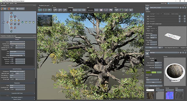
The Tree Window is the large, central area in the middle of the application in the image above. There will be a unique Tree Window for each open model (accessed by tabs along the top).
Toolbar
The toolbar provides access to common modeling operations, rendering control, scene objects, and post-processing operations. Consult the images and the corresponding sections below for details about each toolbar group.
View
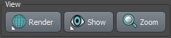
The options in this group (pictured below) control how the model is rendered and what about it is rendered.
Render
This menu allows you to select the current render mode. The menu is populated based on the render mode files located in the “<installation location>/render modes” folder, so it may vary slightly from version to version. In general, you will have a realistic PBR render mode by default (“Standard”), “Scribed” for polygon viewing, and many others for examining all aspects of the material system including ambient occlusion, vertex colors, and raw material values.
| Note: You can write your own render mode! Take a look at the files in the “Render Modes” folder and make one of your own. The shading language is GLSL and most of the input data you would need is passed into the function you'll need to write (RenderMode( )). |
|---|
Show
This menu controls what is rendered. Use the top section to quickly hide any of the geometry types. The next section allows you to control the rendering of “extra” scene objects that may be helpful during the modeling process. Options include:
- Bones: If bones are being computed, use this to see them.
- Hints: Some generator/node types have hint renderings. Parent sensitivity on Leaf Mesh generators and Shape Control on Branch generators are examples.
- Normals: Toggles the display of vertex normals (blue), tangents (red), and binormals (green).
- Disable two-sided rendering: Toggles whether two-sided rendering works on the entire model. Turn this off to help aid in leaf/frond orientation before turning it back on for the final export.
- Cages: Toggles the display of subdivision surface cages (if they are present).
The “Selection style” submenu controls how selected objects are rendered. Options include:
- Toggle highlighting: Toggles selection rendering. Use this to remove selection indicators for close inspection of the model while still being able to edit it.
- Outline, Wireframe, Solid, Box: “Outline” is the default, and “Wireframe” is often used for polygon inspection.
The remaining options toggle the display of the named Tree Window components.
Zoom
This button zooms the camera (along its current view direction) far enough out to see the entirety of the selected object; or the whole model, if nothing is selected.
Scene
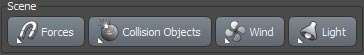
The options in this group (pictured below) provide quick access to scene objects.
Forces
The first two entries in this menu provide options for toggling the display of all Forces and quickly selecting them all. The remaining entries provide mechanisms for selecting existing Forces or adding new ones.
Collision Objects
The first two entries in this menu provide options for toggling the display of all Collision Objects and quickly selecting them all. The next two sections provide mechanisms for selecting existing Collision Objects or adding new ones. The final option, “Generate Collision Primitives,” pops up a dialog that allows you to automatically add Collision Objects to the model.
| Note: Collision objects are available/applicable only in versions of SpeedTree intended for games or other real-time applications. |
|---|
Wind
This menu provides access to the following wind options:
- Edit Wind Properties: This option selects the Fan object and displays its properties in the Property Bar.
- Edit Selected Object's Wind Properties: If an object with wind options is selected, its wind properties will be shown in the property bar.
- Enabled: Toggles wind on and off.
- Gusting: Toggles gusting on and off. This option is not available for all wind types.
- Wind Wizard: Launches the Wind Wizard utility to help set reasonable wind values on your model automatically.
- Set Conditions: This submenu provides a list of preset strength and gusting amounts/frequencies to match common environmental conditions.
- Copy/Paste: Use these options to transfer Fan settings from one model to another.
- Show Fan: This submenu sets when (and if) the Fan is rendered in the Tree Window.
Light
This menu provides access to the following lighting options:
- Edit Light Properties: This option selects the Light object and displays its properties in the Property Bar.
- Presets: This submenu quickly changes all of the lighting colors/intensities to one of several predetermined environments.
- Shadows: Use this submenu to set the shadow quality.
- Ambient Occlusion: Provides options to render and clear per-vertex ambient occlusion.
Resolution
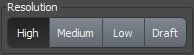
This group (pictured below) is available in VFX builds and enables you to quickly change the polygonal resolution of the model.
Edit
The Edit group (pictured below) contains controls to aid in model creation/editing.
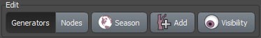
Generators/Nodes
These buttons select which editing mode the application is in. These are very likely the most important buttons on the toolbar, if not in the whole application! Understanding the difference between these modes is essential to the SpeedTree process.
Season
This button pops up the season timeline slider for changing the current season.
Add
Use this button to add new generators to the model. For a more complete description for what this means please look at the “Adding New Generators” section of the Generation Editor.
Visibility
The options in this menu control which parts of the model structure are visible. Use these options to make it easier to see/edit the model.
- Hide/Unhide Selected: Toggle the visibility of the selected generator(s) or node(s).
- Show All: Shows all of the hidden generators and nodes.
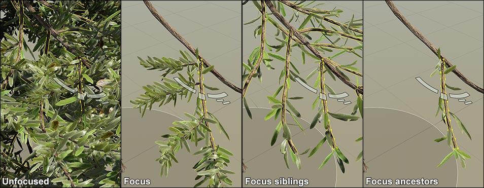
- Focus: Focus operates on the last node clicked in the window. Use these options to isolate parts of the model based on its anatomy as shown in the image below. Standard focus hides everything but the clicked node, its ancestors, and its descendants. “Focus siblings” hides descendants but ancestors remain visible. “Focus ancestors” shows only the clicked node and its ancestors. Batched leaves that are the children of focused objects will always be shown.
- Conceal/Expose: These options show/reveal the deepest level of generators. Use “Conceal” repeatedly to gradually hide generators down to the selected generator level. Use “Expose” to gradually reveal hidden generators.
Post
The Post group (pictured below) provides access to actions to be used on a model after it has been computed.
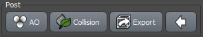
AO
Press this button to compute per vertex ambient occlusion on the model.
Collision
Use this menu to set leaf collision options for the model.
Export
Press this button to export the model as a mesh.
Collapse
This button toggles whether names appear with the icons on the toolbar. Use this options to save room on smaller displays.
Viewports
These are the 3D and 2D regions where the tree is rendered. The tree window can show a single viewport, two viewports (horizontal or vertical), or four viewports.
Layout
By default, there is only a single viewport visible (perspective). To enable other views, right-click in the tree window and select the pull-right menu “Layout.” Other configurations can be found there as well. You can change the active viewport from the right-click menu as well.
Isolating a Single Viewport
A shortcut for isolating a single viewport is double-clicking the middle mouse button inside any viewport. Double-Middle-Click again to go back to the previous viewport arrangement.
Projection Types
There are four projection types to choose from per viewport: perspective, XY plane, XZ plane, and YZ plane. The perspective projection is the default view, and the other three are orthographic projections from the appropriate axis. Extra types are added when importing cameras from an FBX file.
Splitters
Splitters are the horizontal and vertical lines that divide the viewports.
Sizing the Viewports
The viewports can be resized by adjusting the splitters. Left-click and drag the horizontal splitter up and down to change the height of the viewports. Left-click and drag the vertical splitter left and right to change the width of the viewports. Left-clicking and dragging the region where the splitters cross allows width and height to be changed simultaneously. The splitters can be reset via the “Layout” portion of the right-click menu.
Tree Window Overlays
There over several instances where extra controls and data are shown over the window contents.
Fan
 The Fan displays the directional influence and strength of the wind. Rotate the Fan by either clicking on it and using the rotate manipulator, or by holding down the “G” key and dragging the left mouse button. Control wind strength by holding down “G” and dragging the middle mouse button. Right-click in the Fan area for quick access to wind functions, such as copy/pasting wind, or disabling gusting.
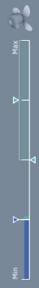
Wind Indicator
When wind is on, a graphical visualization of wind strength and gusting is displayed below the Fan icon. The wind indicator has three sections:
Strength
The lower left, blue triangle represents the current wind strength setting. Change the constant wind strength here, if desired.
Gust Strength/Variance
The higher left cyan triangle represents gust strength. When a gust occurs, wind strength will reach this value, give or take the variance. The gust variance is visualized with a cyan bar extending up and down from the gust strength.
Gust Frequency
The right cyan triangle indicates gust frequency. The higher this value, the more often a gust will occur.
Light
The Light displays the directional light rotation, the light color, and the light intensity. The Light is a screen-space object that rotates with the camera, making light rotation relative to the current view. The Light can be rotated either by clicking on it and setting the manipulator mode to “Rotate”, or by holding down the “V” button and dragging the left mouse button (side-to-side orbits the Light while up and down movements alter the slope of the Light angle).
LOD Indicator
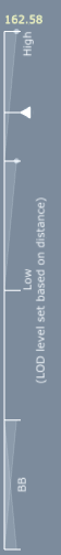 If LOD (level of detail) is enabled and the preview style is set to “Manual,” (both are tree generator properties), the LOD Indicator (bottom left corner of the tree window) is exposed and is able to control the current level of detail state. Drag the point from highest LOD to lowest LOD to preview LOD transitions at a fixed distance (or hold the CTRL key while dragging the left mouse button up and down).
If the preview style is set to “Use Screen Area,” the LOD Indicator is still visible, but it is disabled from editing. Zoom the camera away from the tree to see it transition between the near and far LOD property values (another tree generator property). Lines are displayed on the LOD Indicator for the level of detail count and transition ranges.
Axis Indicator
The Axis Indicator is a representation of the major axes (X, Y, and Z) from the perspective of the current camera. Toggle its visibility via the tree window properties.
Navigation
There are three modes of navigation: “Standard,” “Trackball,” and “Traveler.” To switch between navigation modes, right-click in the window and select the pull-right menu “Navigation.”
Standard
Standard navigation mode allows users to manipulate the scene as though it were surrounded by an imaginary trackball whose “up” vector is always aligned with the global 'Z' axis. This navigation type makes use of a pivot point to control where the camera is looking and to define the point of rotation.
Panning
Start panning by pressing and holding the middle mouse button anywhere in the viewport. Move the mouse left, right, up, and down to move the viewpoint. Release the middle mouse button to stop panning. Panning moves both the viewpoint and the pivot point simultaneously.
Rotating
Start rotating by pressing and holding the left mouse button anywhere in the viewport. Move the mouse left and right to rotate the viewpoint around the 'Z' axis of the pivot point. Move the mouse up and down to rotate the viewpoint above or below the pivot point. Release the left mouse button to stop rotating. Only the viewpoint changes during rotations.
Zooming
Start zooming by pressing and holding the left and middle mouse buttons anywhere in the viewport. Move the mouse up to back away from the pivot point. Move the mouse down to move closer to the pivot point. Release both buttons to stop zooming.
An alternative to dragging the mouse with both buttons down is to roll the mouse wheel. Roll the mouse wheel up to back away from the pivot point. Roll it down to move closer. It is sometimes desirable to move both the pivot point and the viewpoint at the same time while zooming (i.e., “push” the viewer and pivot point through an object to another one so that future pivots will be around the new object). To do so, hold the SHIFT key down while performing a typical zoom operation.
Alternative Control Schemes
Some people prefer to use control schemes familiar to them from other applications. Below is a table of the available control schemes. The control scheme can be changed on the Application Preferences dialog.
Autodesk® Maya® Maya-style controls will be used:
  Rotate - press and drag alt+LMB
  Pan - press and drag alt+MMB
  Zoom - press and drag LMB+MMB, scroll wheel, or alt+RMB
Autodesk 3ds Max® 3ds Max-style controls will be used:
  Rotate - press and drag alt+MMB
  Pan - press and drag MMB
  Zoom - press and drag alt+CTRL+MMB or scroll wheel
Trackball
Trackball navigation mode allows users to manipulate the scene as though it were surrounded by an imaginary trackball (this time, without an up vector restriction). This navigation type makes use of a pivot point to control where the camera is looking and to define the point of rotation.
Panning
Start panning by pressing and holding the middle mouse button anywhere in the viewport. Move the mouse left, right, up, and down to move the viewpoint. Release the middle mouse button to stop panning. Panning moves both the viewpoint and the pivot point simultaneously.
Rotating
Start rotating by pressing and holding the left mouse button anywhere in the viewport. Move the mouse left, right, up, and down to rotate freely around the pivot point. Release the left mouse button to stop rotating. Only the viewpoint changes during rotations.
Zooming
Start zooming by pressing and holding the left and middle mouse buttons anywhere in the viewport. Move the mouse up to back away from the pivot point. Move the mouse down to move closer to the pivot point. Release both buttons to stop zooming.
An alternative to dragging the mouse with both buttons down is to roll the mouse wheel. Roll the mouse wheel up to back away from the pivot point. Roll it down to move closer. It is sometimes desirable to move both the pivot point and the viewpoint at the same time while zooming (i.e., “push” the viewer and pivot point through an object to another one so that future pivots will be around the new object). To do so, hold the SHIFT key down while performing a typical zoom operation.
Traveler
Traveler navigation mode allows users to navigate a scene as though they were a participant in it. Unlike the previous navigation modes, there is no pivot point. Instead, mouse motions are mapped to actions that move an imaginary traveler through the scene as follows:
Walking
Start walking by pressing and holding the left mouse button anywhere in the viewport. Move the mouse up to walk forward and down to walk backward (faster mouse moves result in faster walking). Move the mouse left and right to change direction. Release the mouse button to stop walking. Only the viewpoint changes during rotations. Walking motion is typically parallel to the 'XY' plane. To move in the direction the traveler is looking, hold down the SHIFT key while performing a regular walk action.
Strafing
Strafing is the act of stepping sideways without changing the direction the viewer is looking. Start strafing by pressing and holding the middle mouse button anywhere in the viewport. Move the mouse left to strafe left and right to strafe right. Release the middle mouse button to stop strafing.
Changing Height
It is possible to change the height of the imaginary traveler (distance along the 'Z' axis of the viewpoint). Change the height by pressing and holding the middle mouse button anywhere in the viewport. Move the mouse up to make the traveler taller and down to make the traveler shorter. Release the middle mouse button to stop changing the height.
Looking Up and Down
Start looking by pressing and holding the left and middle mouse buttons anywhere in the viewport. Move the mouse left, right, up, and down to look around without changing the position of the viewpoint. Release both buttons to stop looking.
Window Properties
There are a number of properties that control the viewports, background images, and other aspects of the Tree Window. Access these properties via the Window pulldown menu or selecting the “Window Properties” on the Property Bar when nothing is selected.