Mesh Anchors
Mesh anchors specify attachment points on mesh assets. These anchors can then be used to generate meshes as children of other meshes. The most common use for this technique is for building image-based branch and leaf structures for low polygon models. The image below shows mesh anchors in use on a model and the meshes as they appear in the Cutout Editor.
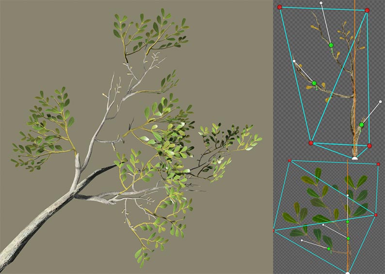
The only 3D branch in this image is the one protruding from the lower left. The rest are meshes with branch and leaf structure maps created using the cluster technique. Notice the green dots and white orientation lines in the mesh cutouts. These are the anchor points and the direction the “Y” axis of their children will face by default. Mesh anchors are always assigned in the Cutout Editor.
Now let's examine this image of the generator hierarchy for this model.
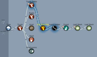
The last 3D branch is selected. The remainder of the model comprises fronds and leaf meshes. When a generator that uses meshes is applied to another generator that uses meshes, standard generation properties do not apply. Instead, they are replaced by a single generation property called “Anchors,” pictured below.
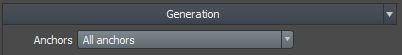
Each mesh anchor is given an integer ID from 1 to 5. Use the “Anchors” property to restrict generation to a particular anchor number, if desired. Anchor numbers are assigned by right-clicking the anchor in the Cutout Editor. The “Shared” generation properties like “First” and “Last” still apply.
Best Practices
The following list contains some tips to keep in mind when using mesh anchors.
- The only place to edit mesh anchors is the Cutout Editor – they cannot be assigned to meshes created in other applications.
- The cluster technique is often the easiest way to create the maps needed for this technique. There are cluster models in the samples folder to help get you started.
- Mesh anchors work even if the parent mesh has been folded, curled, flipped, or otherwise deformed.
- When stacking leaves on leaves it may be necessary to zero out the wind (or at least carefully tune the profile curve) on the base leaf to avoid separation when wind is enabled.
- If your meshes have multiple LODs, mesh anchors must be assigned to each LOD. They can also be in different places, which may help when using multiple mesh LOD levels to control the polygon count at the highest LOD.
- This technique is far more commonly used in real-time models than it is for VFX models.